

PAPI Systems
A PAPI, precision approach path indicator, is a row of ground units beside the runway that shows a pilot on final approach whether the aircraft sits above, on, or below the correct glide path through red and white lights. Northlane Solutions supplies PAPI systems built to ICAO Annex 14 Volume I for runway and heliport approaches across Saudi Arabia.
Inside the PAPI Systems
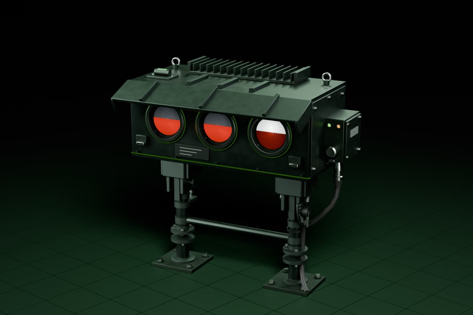
Download technical datasheet (PDF)A PAPI unit is an assembled optical fixture rather than a single lamp, combining a projector housing, colour filter, light source, and aiming mechanism into one field-mountable unit. Each part has a distinct role in producing a sharp, correctly angled red and white beam, and the whole unit sits on a frangible mount wired into the runway's constant current series circuit.

01
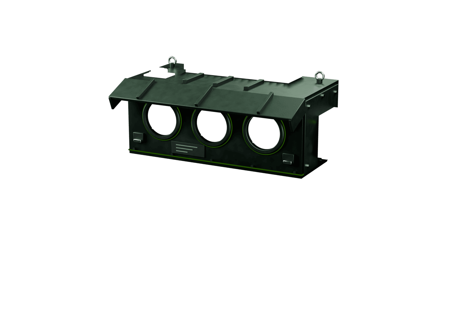
Optical Projector Box
Houses the optical train that shapes the light source's output into a narrow, high-intensity beam. Its internal geometry sets the sharp transition line between the red and white sectors that a pilot reads on approach.
02
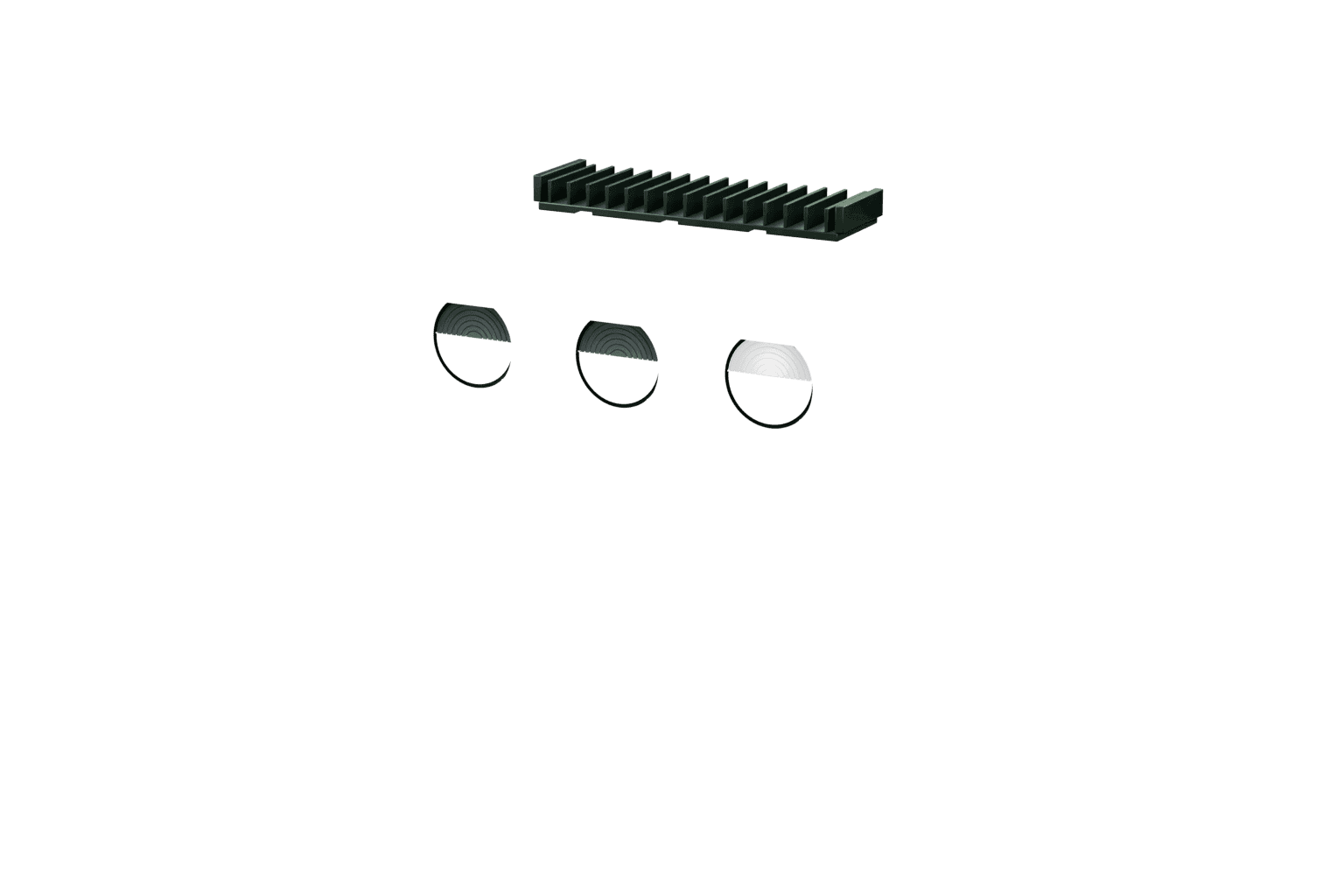
Colour Filter Assembly
A precision red filter fitted across part of the beam path to split the projected light into red and white halves. Filter alignment directly determines how sharp and stable the colour transition appears from the cockpit.
03
LED Light Source
Provides the high-intensity output the optical projector shapes into a beam. An LED source holds its intensity and colour output steady over long service life compared with older lamp technology.
04
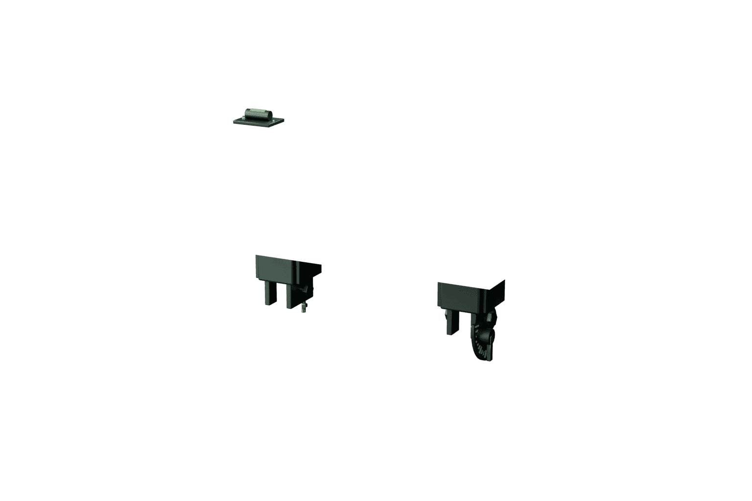
Angular Tilt Mechanism
A fine adjustment mechanism that sets and locks the unit's vertical aiming angle against the runway's design glide path. Correct tilt setting is what makes the red/white transition line correspond to the intended approach angle.
05
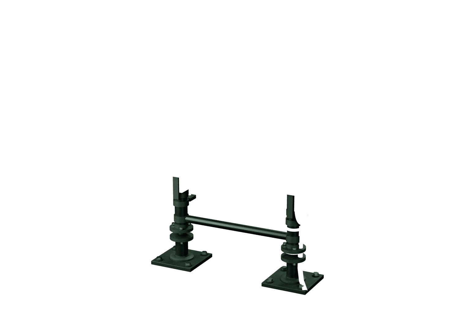
Frangible Mounting Legs
Low-profile support legs designed to break away cleanly on impact, meeting aerodrome frangibility requirements for objects near a runway or approach surface. This limits risk to an aircraft that inadvertently contacts the unit.
06
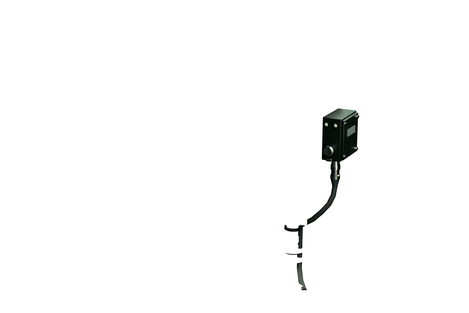
Power and Control Interface
Connects the unit to the runway's constant current series circuit and, where fitted, to the brightness step control signal. It is the electrical link between the PAPI unit and the wider airfield lighting circuit.
FULLY ASSEMBLED
PAPI Systems
Explore the assembly
01
Optical Projector Box
Houses the optical train that shapes the light source's output into a narrow, high-intensity beam. Its internal geometry sets the sharp transition line between the red and white sectors that a pilot reads on approach.
02
Colour Filter Assembly
A precision red filter fitted across part of the beam path to split the projected light into red and white halves. Filter alignment directly determines how sharp and stable the colour transition appears from the cockpit.
03
LED Light Source
Provides the high-intensity output the optical projector shapes into a beam. An LED source holds its intensity and colour output steady over long service life compared with older lamp technology.
04
Angular Tilt Mechanism
A fine adjustment mechanism that sets and locks the unit's vertical aiming angle against the runway's design glide path. Correct tilt setting is what makes the red/white transition line correspond to the intended approach angle.
05
Frangible Mounting Legs
Low-profile support legs designed to break away cleanly on impact, meeting aerodrome frangibility requirements for objects near a runway or approach surface. This limits risk to an aircraft that inadvertently contacts the unit.
06
Power and Control Interface
Connects the unit to the runway's constant current series circuit and, where fitted, to the brightness step control signal. It is the electrical link between the PAPI unit and the wider airfield lighting circuit.
| Body material | Cast aluminium alloy housing with corrosion-resistant outdoor finish |
| Ingress protection approach | Sealed optical chamber designed for continuous outdoor exposure |
| Power options | Constant current series circuit supply via isolating transformer, matched to the runway lighting circuit |
| Control compatibility | Brightness step selection via ALCMS or manual regulator step control |
| Mounting | Frangible low-profile ground mount per aerodrome obstacle safety requirements |
| Operating environment | Rated for sustained high-temperature, dust, and sand exposure |
| Beam configuration | Four-unit or two-unit array with red/white sector split per ICAO Annex 14 Volume I |
How a PAPI works
A PAPI system uses a row of four (or sometimes two for smaller aerodromes and heliports) ground-mounted units set beside the runway near the threshold, each projecting a beam split between red and white light at a slightly different vertical angle. A pilot on the correct glide path sees two units showing red and two showing white; above the glide path the count shifts toward more white units, and below it shifts toward more red, giving an immediate, unambiguous visual read of vertical approach position without needing to interpret a needle or instrument display.
Standards and siting
ICAO Annex 14 Volume I sets the visual guidance requirements a PAPI installation must meet, including unit spacing, beam transition sharpness between the red and white sectors, and the angular tolerance for each unit's aiming point relative to the design glide path angle. Siting a PAPI correctly is a survey-driven exercise tied to the runway's actual approach surface and any obstacle clearance requirement in the approach path, not a fixed offset applied the same way on every runway. GACAR Part 139 applies the same ICAO reference at licensed Saudi aerodromes.
Fixture and power considerations
PAPI units run on the same constant current series circuit logic as the rest of the runway lighting string in most installations, so circuit sizing needs coordinating with the runway edge and threshold lighting design rather than treated as an isolated fixture group. Northlane Solutions sources PAPI units with LED sources for consistent beam intensity and colour transition over the fixture's service life, housed to withstand outdoor exposure across Saudi Arabia's heat, dust, and sand conditions without the beam-cutoff sharpness degrading over time, a common failure mode in poorly sealed older units.
Turnkey delivery
Northlane Solutions delivers PAPI systems as a complete scope: unit supply, siting survey and aiming angle calculation against the approach design, installation, circuit integration with the runway lighting string, and commissioning flight-check coordination support. Units are sourced from established international aviation lighting manufacturers, quoted in USD and SAR.
What to send for a quote
Send the runway's approach design data, including the design glide path angle, threshold crossing height requirement, and any obstacle survey affecting siting, along with the existing or planned runway lighting circuit configuration. Northlane Solutions returns a unit and siting recommendation with lead time and pricing.
Specifications
- ✓Four-unit or two-unit ground array per ICAO Annex 14 Volume I visual guidance requirements; GACAR Part 139 applies the same reference on licensed Saudi aerodromes
- ✓Red/white beam split with defined transition sharpness, aiming angle set against the runway's design glide path
- ✓Siting determined by survey against the approach surface and any obstacle clearance requirement, not a fixed offset
- ✓LED source for consistent beam intensity and colour transition over service life
- ✓Circuit integration with the runway lighting series circuit and constant current regulator
- ✓Weatherproof housings for sustained outdoor exposure across Saudi heat, dust, and sand conditions
Frequently Asked Questions
How does a pilot read a PAPI on approach?+
On the correct glide path, a standard four-unit PAPI shows two units red and two white. If the aircraft is above the glide path, more units show white; if below, more show red, giving an immediate visual read of vertical position without an instrument.
How is a PAPI system positioned and angled for a specific runway?+
PAPI siting is survey-driven, tied to the runway's actual approach surface, the design glide path angle, and any obstacle clearance requirement in the approach path. It is not a fixed offset applied identically to every runway, which is why an accurate approach survey precedes unit installation.
Who supplies PAPI systems for runways in Saudi Arabia?+
Northlane Solutions sources and supplies PAPI units built to ICAO Annex 14 visual guidance requirements, with siting survey, installation, and commissioning support, for runway and heliport approach projects across the Kingdom.
What is the role of the Optical Projector Box in PAPI Systems?+
Houses the optical train that shapes the light source's output into a narrow, high-intensity beam. Its internal geometry sets the sharp transition line between the red and white sectors that a pilot reads on approach.
What is the role of the Colour Filter Assembly in PAPI Systems?+
A precision red filter fitted across part of the beam path to split the projected light into red and white halves. Filter alignment directly determines how sharp and stable the colour transition appears from the cockpit.
What is the role of the LED Light Source in PAPI Systems?+
Provides the high-intensity output the optical projector shapes into a beam. An LED source holds its intensity and colour output steady over long service life compared with older lamp technology.
What is the role of the Angular Tilt Mechanism in PAPI Systems?+
A fine adjustment mechanism that sets and locks the unit's vertical aiming angle against the runway's design glide path. Correct tilt setting is what makes the red/white transition line correspond to the intended approach angle.
What is the role of the Frangible Mounting Legs in PAPI Systems?+
Low-profile support legs designed to break away cleanly on impact, meeting aerodrome frangibility requirements for objects near a runway or approach surface. This limits risk to an aircraft that inadvertently contacts the unit.
What is the role of the Power and Control Interface in PAPI Systems?+
Connects the unit to the runway's constant current series circuit and, where fitted, to the brightness step control signal. It is the electrical link between the PAPI unit and the wider airfield lighting circuit.
Who supplies PAPI Systems in Saudi Arabia?+
Northlane Solutions (Northlane Solutions Company) supplies PAPI Systems across Saudi Arabia, including Riyadh, Jeddah, Dammam and Jubail. Send your specification and quantities to info@northlanesolution.com for a quotation.
Related products
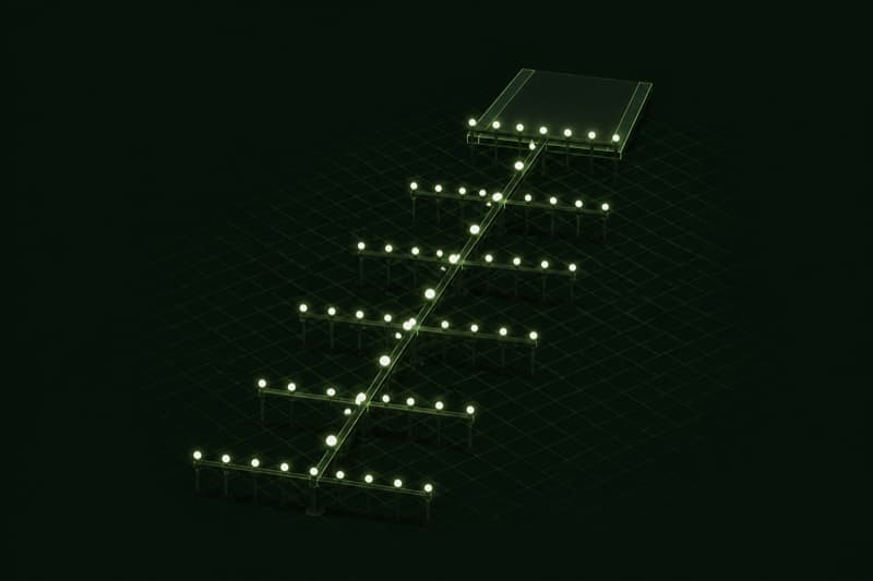
Approach Lighting Systems
An approach lighting system extends a defined pattern of light bars, and on longer configurations sequenced flashing lights, outward from the runway threshold along the extended centreline, giving a pilot on final approach horizontal guidance before the runway itself becomes visible. Northlane Solutions supplies approach lighting sized to the runway's approach category, engineered to ICAO Annex 14 Volume I.

Airfield Guidance Signs
Airfield guidance signs, illuminated mandatory instruction, location, and direction signs placed along runways and taxiways, tell a pilot where they are and what boundary or intersection lies ahead, backing up ground lighting and radio instructions with a fixed visual reference. Northlane Solutions supplies illuminated airfield signage engineered to ICAO Annex 14 Volume I sizing and legend requirements across Saudi Arabia.

Runway Edge Lights
Runway edge lights are the fixed white fixtures spaced along both sides of a runway that define its usable width at night or in low visibility, switching to yellow along the final section approaching the runway end on longer runways. Northlane Solutions supplies runway edge light fixtures engineered to ICAO Annex 14 Volume I, elevated and in-pavement, across Saudi Arabia.

Threshold & Runway End Lights
Threshold and runway end lights mark where the landing surface begins and ends, showing green to an approaching aircraft and red to one departing off the far end. Northlane Solutions supplies threshold and end light fixtures, wing-bar arrays, and associated circuit components engineered to ICAO Annex 14 Volume I, for airfield and heliport projects across Saudi Arabia.
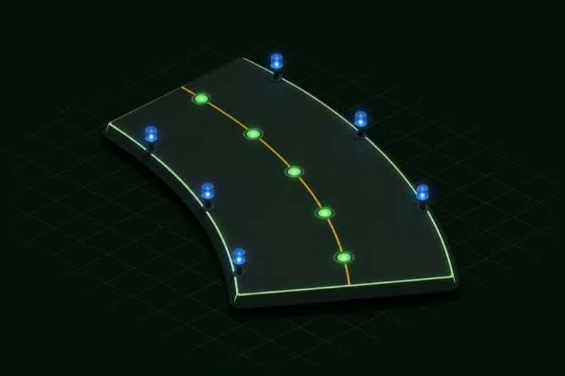
Taxiway Lighting
Taxiway lighting, blue edge lights and green centreline lights, guides an aircraft between the runway and apron on the ground at night or in low visibility. Northlane Solutions supplies taxiway edge and centreline fixtures built to ICAO Annex 14 Volume I, including elevated and in-pavement centreline options, as turnkey supply and installation for airfield and heliport projects across Saudi Arabia.
Guides
PAPI Systems Explained: How Four Light Units Guide an Approach
What a PAPI system is, how its four light units signal approach slope, the siting and calibration basics that determine accuracy, and the recurring maintenance obligations that keep it airworthy.
Helipad Lighting Requirements: Perimeter, Floodlighting, Beacons and Wind Cones Under ICAO
What ICAO Annex 14 Volume II and GACAR Part 138 expect from helipad lighting, covering perimeter lights, floodlighting, heliport beacons and illuminated wind cones, explained qualitatively without invented specification values.
Saudi Aviation Infrastructure Glossary: A to Z Terms Buyers Need
A practitioner glossary of the aviation infrastructure terms buyers meet on Saudi projects, covering airfield ground lighting, heliport design, obstruction lighting, arresting systems and the regulatory acronyms behind GACAR and ICAO Annex 14.
How Heliport Approval Works in Saudi Arabia Under GACAR Part 138
How GACAR Part 138 heliport approval works in Saudi Arabia: who applies, what an aeronautical study covers, the forms involved, and the typical gates a project moves through before an operator can use a helipad.